🔧 Elevate Your Projects with AITRIP's I/O Magic!
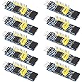
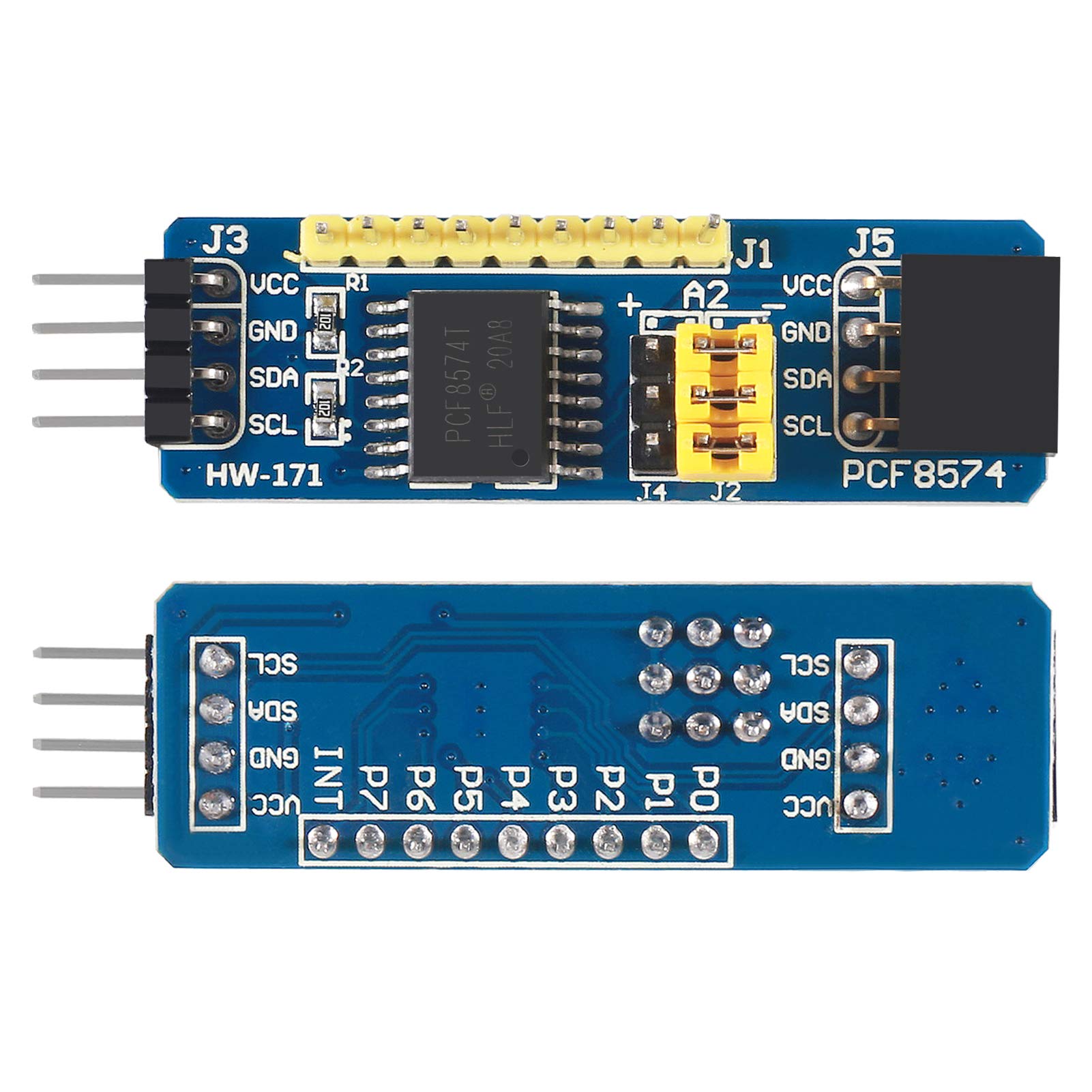
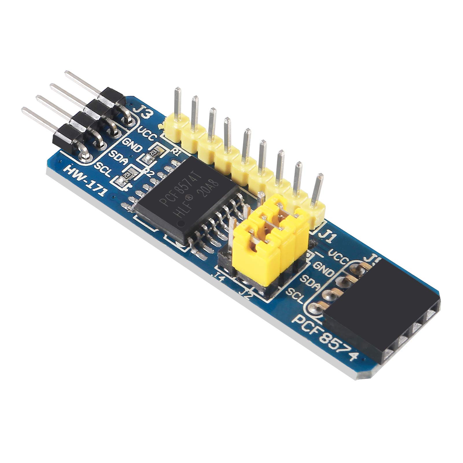
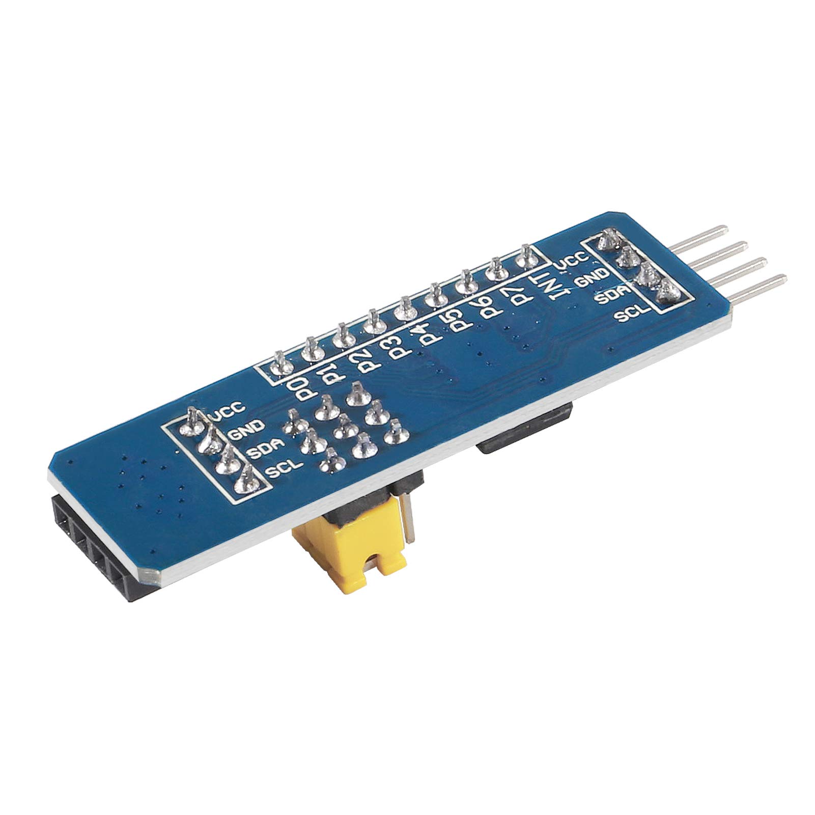
The AITRIP 10pcs PCF8574 IO Expansion Board is a powerful I2C-bus evaluation module designed for Arduino and Raspberry Pi enthusiasts. With its 8-bit parallel port output, this expansion board allows for significant I/O resource enhancement, enabling up to 64 simultaneous connections. Ideal for developers looking to maximize their project capabilities, this lightweight and compact module is a must-have for any tech-savvy professional.
Brand | AITRIP |
Item Weight | 2.08 ounces |
Package Dimensions | 6.1 x 4.8 x 0.98 inches |
Color | Blue |
Manufacturer | AITRIP |
ASIN | B08YNBZQ5S |
Date First Available | March 11, 2021 |
D**S
Great value for the price.
I ordered 10 of these, and have used several. In each case, they simply worked. No problems.
P**L
Great Value!
Good quality product! Lots of interesting interfacing uses for this device! Small and well made.
K**R
Work very well and saves miles of wiring.
I have a setup that uses about 40 of these with a single Raspberry Pi, and they are solid. I think I had only one that was troublesome in the whole batch and that might have only been a miswire or screwed up address jumper. These are so inexpensive I didn't even bother to troubleshoot it.They work great with the TCA9548A I2C IIC Multiplexer 8 Channel Expansion Board to give you a ridiculous number of devices on one I2c bus.
P**E
Simple and cheap
These are probably the simplest possible I2C GPIO expanders you could get. Unlike fancier ones like the MCP23017, these don't have configuration or direction registers - in fact, they don't have any registers at all! Performing a single byte I2C read from one of these will read the state of the 8 data pins, and writing a single byte will set them. Writing a "0" will pull the pin strongly to ground, and writing a "1" will pull it to VCC through a 0.1 mA current source (equivalent to a 50k ohm resistor when VCC is 5v). This means that they are not true tri-state GPIOs, but they will work for most purposes. On reset, the outputs are set to "1" so they can be used as inputs.Whenever you perform a read, the value that gets read is latched into an internal register (call it L). This pin reflects the value of NAND(P0 XOR L0, P1 XOR L1, ..., P7 XOR L7). So whenever one of the pins doesn't match the last value read, INT is pulled low. You can connect it to a Raspberry Pi or Arduino GPIO, enable the internal pull-up, and configure an interrupt on the falling edge to detect a change on any pin.This works equally well with 5v or 3.3v VCC.This board has a 1K pull-up to VCC for both SDA and SCL.I do wish the layout of the board were a little better. I appreciate that it has a connector on both ends so they can be directly chained, but connecting it to a solderable breadboard is a pain because the VCC/GND/SDA/SCL pins are at 90 degrees from the data pins and don't 100% line up with a 0.1inch grid.
F**A
Excellent attention and quick response.
There was a little problem with the product.I sent a message to the seller and in a very friendly and fast way I solved it.Thank you very much for the quick response and kind attention.Recommended seller and product.
Trustpilot
3 weeks ago
1 month ago