


🚀 Power your next-gen IoT hustle with the ultimate dual-core connectivity beast!
The JZK ESP-32S ESP32 Development Board is a compact, ultra-low power dual-core MCU module featuring 2.4GHz WiFi and Bluetooth dual-mode connectivity. It boasts 4MB SPI Flash, 520KB SRAM, and a rich set of integrated peripherals including capacitive touch, SD card, Ethernet, and multiple communication interfaces. Designed for seamless development with onboard CP2102 and Arduino IDE support, it’s perfect for professional-grade IoT, sensor networks, and audio streaming projects.
| ASIN | B071JR9WS9 |
| Box Contents | 1 x ESP32 development module |
| Brand | JZK |
| Brand Name | JZK |
| CPU speed | 8E+1 MHz |
| Compatible Devices | Smartphone, Personal computer, Camera |
| Connectivity technology | Bluetooth |
| Customer Reviews | 4.5 out of 5 stars 773 Reviews |
| Manufacturer Part Number | JZK-75639 |
| Memory Storage Capacity | 4 MB |
| Memory storage capacity | 4 MB |
| Model Name | ESP-32S |
| Model Number | JZK |
| Model name | ESP-32S |
| Network Connectivity Technology | Bluetooth |
| Operating System | Linux, Windows |
| Processor Brand | Espressif Systems |
| Processor Count | 2 |
| Processor Speed | 8E+1 MHz |
| RAM Memory Installed | 520 KB |
| RAM Memory Technology | SRAM |
| RAM memory installed size | 520 KB |
| Total USB Ports | 1 |
| Wireless Compability | Bluetooth |
P**O
Perfect ESP32 with no hassle flashing
This ESP32 dev board is a gem! I needed its Bluetooth functionality, and it worked like a charm. Unlike other suppliers, there’s no need to fuss with the reset button – it’s super smooth to use. Other features like WiFi, fast processor, and large flash make this the ultimate Arduino replacement. Plus, it’s budget-friendly, and perfect use with your IOT projects. It’s easy to connect sensors, and phones to communicate with other devices. Honestly, I can’t see any negatives. For tinkerers enthusiasts, this ESP32 board is a winner. It’s great for many projects due to it's diverse features. Also, the Arduino plays well with the IDE, allowing for faster development.
F**T
Absolute bargain
Disclaimer - I received a full refund after reporting a minor fault, making my unit effectively free. This is probably the lowest one-off price you'll pay for an ESP32. EPS32s a great. Highly recommended. It's a fully functional and easy to use Bluetooth/WiFi module with a micro-controller built in; or a micro-controller with a WiFi module built in - whatever way you want to look at it. Forget Arduinos and shields, this is everything in a tiny package. The hardware is open source (credit: Wei Wang/doit.am), so there are many variations to choose from. This PCB version is 0.1" wider than some ESP32 modules (see photo), which leaves rooms for mounting holes but with molex pins attached it's a row too wide for a standard prototyping board. Mine arrived with a fault in the molex pins, which were soldered on at a funny angle. I got a full refund without even asking for one so I can't fault the customer service. I'm assuming mine just slipped through quality control, but as I will probably remove the pins anyway (a complete pain to do) so I can attach wires to the PTH I could have lived with it. So in spite of the slight flaw, the customer service has restored it to five star. The extra width allows the edge pins to be silk-screened with labels, which is useful. Many of the pins are GPIO, and I believe there are three ACIAs (UARTS) built in; one of which is used by the USB via a converter chip. The whole thing runs beautifully cool. For software, the Arduino IDE "just works" with it, once you've installed the board package. And this includes complex libraries allowing you WiFi, DNS and IP socket drivers - including encryption on the WiFi and SSL. I absolutely love these boards. The picture is this board (right) next to a different, narrower, ESP32 board on the left. Both use the same ESP32 model at the centre. It shows the prototyping board problem, which is easy enough to overcome with a different prototyping board (or two of them).
A**R
Works well, but it's the "old" USB connector (not USB-C) and you'll need to use wider breadboard
Works well, just remember it's the "old" USB connector (not USB-C) and you'll need to use a wider breadboard, or two side by side. USB takes care of the reboot on code deployment, so you don't often have to hit the "boot" or "EN" buttons. can't find schema to control the red "always on" LED, however there's a small blue onboard LED which maps to GPIO-2. Never used these boards before but had it up and running, controlling LED, LCD panel and interfaced to home wifi within a couple of hours.
A**R
Well made ESP32 board for the price, micro USB connector, too wide for standard breadboards
First impression: well made board. It has the older micro-USB connector for which I had to dig through my old cables box to find a suitable data-capable one. I am deducting a star because the usb type is not mentioned anywhere in the description. The board is too wide to fit normally on standard breadboards. However it conveniently has 3V3, GND, both I2C data and clock as well as a bunch of GPIO all on one side, which means that only one side of the board has to be plugged on the breadboard (see attached image for a small breadboard where I prototyped an air quality monitor with an I2C SCD40 sensor, an OLED screen and a push button). Despite what is mentioned on other reviews I flashed my code straight from the Arduino IDE (after installing the ESP32 Dev Module library) with no need to old any buttons on the board during flashing. Could I have received a new revision? Overall, a good quality, (not so) little board for the money. Just make sure you have a micro usb cable at hand!
V**I
Perfect.
It's a teeny tiny dev board but perfect for an ESPhome Bluetooth proxy. A shame it still uses Micro USB though. Also needs a case which you have to buy separately. Don't leave the PCB bare.
G**T
Excellent value for money
Bought this to start tinker with and for the value it is excellent Easy to setup and works with Arduino IDE, or VSC ode with the Platform IO extension One thing to watch is to ensure your USB cable is a data cable and not just a charging cable. Ideal for anyone who wants to get into creating little electronic projects.
M**O
The Internet of Dings
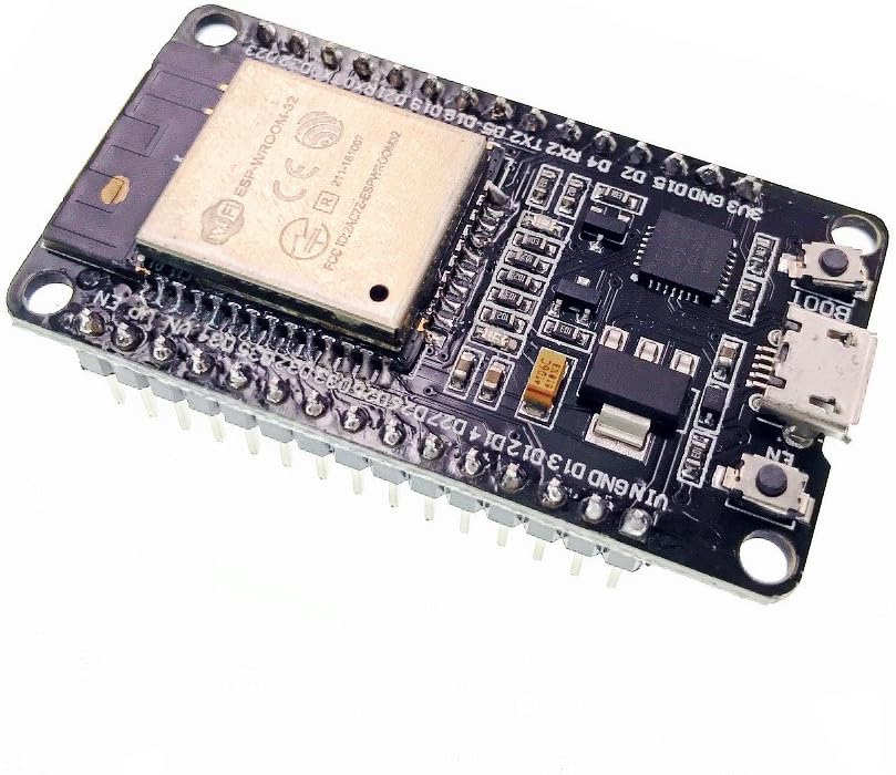
The good, the bad and the ugly. First the good. This is a very low-cost but very powerful development board. It has two main processor cores capable of running ARM instructions at typically one instruction per cycle so it can really perform despite the modest clock speeds. It has WiFi, Bluetooth, Bluetooth Low Energy, magnetic sensor on board, analog ports, capacitive touch sensors and a ultra-low power co-processor which can, in theory, run for months on a single coin cell. (The main processor goes into deep sleep while it does this and is only woken by the co-processor when needed so this is a great way to save power in portable devices.) It’s cheap too – very cheap for what you’re getting. There are a lot of projects out there for the Raspberry Pi using electronics but the vast majority don’t need something as powerful as the Pi – not even the Pi Zero. This board is the complete opposite. While it’s not massively powerful (although it outperforms, say, the computers that put men on the moon) it has loads of sensors, it’s far cheaper and often far more practical too. Now the bad. The instructions: there aren’t any. I mean not a jot. The best we get from this device is a reference to a Github page that hasn’t been touched in over two years and probably longer. This is for the manufacturer’s uRTOS (micro real-time operating system) and the Lua programming language. But using that means building your own toolchain and, I assume the rest of the stuff, from scratch and most of us don’t have time for that. We just want to stick it into a breadboard and play, right? Thankfully, the Internet and Limor “Lady Ada” Freid come to the rescue in the form of loads of tutorials and pre-made libraries so, with a little bit of searching you can find out that it is indeed possible to plug this into an Arduino IDE and get cracking. And the Ugly And this folks, is where it gets really, really ugly. There’s a TL;DR at the end if you’re inclined. I’ve now got two of these (which might leave you wondering how after the tone of this review) but allow me to explain. There are a lot (and I mean A LOT) of clone boards out there based on this chipset and not all of them are created equal. Some are very good, some … not so much so and this is one of them. When the first one arrived (with a little ding in the shield) I was worried that it had gotten damaged in the post but gave it a go anyway. Nada. Not an electronic sausage. It powered up – the red LED glows but the computer didn’t see the UART tethered to the USB connection. Things were not looking good. So, with minutes to spare (and a deadline to meet) I ordered another and Amazon delivered (brilliantly) as ever. In goes the new one and … ooops. Another faulty one? Can’t be. After some searching and two more micro-USB leads later I find myself able to communicate with the UART, so maybe the first one isn’t jiggered after all. Sure enough, the UART responds and I feel a bit foolish for not checking the wires in the first place. So it’s all my fault and off I go to program my first Arduino sketch. It should be said that there is a system to include these development boards into the Arduino IDE but that’s really something better explained by people who have made videos about it. Once you’re set to go, you hit the upload button and wait. Like magic, the little board fired into life and stuttered a bunch of integral signs all over the serial monitor. As dumb as I am, I figured that couldn’t be right. The blue LED (used in some sketches for testing, stubbornly sat there… dull, uninterested and unlit.) So I popped the “dead” board in to see what would happened and … nothing. Although Linux (I’d moved from Windows because I prefer the ease of Linux for hardware development) and held my breath and … Things went from bad to “oh, so it was dead all along”. No amount of begging, pleading or generally swearing in the direction of this little beastie was going to get the sketch to upload. Noooooo! “Right… it’s going back to Amazon!” I figured and filling in a tart response to why I was sending it back. Meanwhile, the other board also developed an eerily similar fault. Sometimes sketches would upload, other times the same one would stall, falter and on occasion not even transfer at all. Perchance in my fury I happened across Mr. D. Lambert’s review where he mentioned that it was necessary to hold the “boot” button – it’s a tiny switch as one might expect – until the sketch starts to upload. You have to do WHAT?! But sure enough, holding down boot the serial console sparked into life and a whole load of technical details spat down the link – in English no less – giving all manner of detail about the board, WiFi and so on. That wasn’t expected, but again, the other board behaved slightly differently – but I did notice that even the working board experience a very slight delay before the sketch started to upload – unless I held boot. That just didn’t make sense but while I was looking for tutorials and examples (I’m selectively lazy, it’s a good trait in programmers) I chanced upon a site detailing soldering (!) a 100mfd capacitor close to the processor case and down to the EN pin. We’re talking some delicate soldering there that’s well outside the scope that most makers would want to attempt – even me and I used to be very good at it. These days 100mfd capacitors are cheap and fairly small but getting one at 1am when even Amazon has stopped taking orders… well. Out comes the radio spares box after some rummaging, I found some very old (recovered) 10mfd caps wasting away in the corner of a draw! Eureka! Out with the soldering iron. But another look at the board and it’s a hard no: soldering with a 25+ year old Antex CX18 and a tip that’s probably being used to melt plastic… and no sponge. Maybe not. Somewhat bizarrely, the choice of where to solder this capacitor turns out to be less important than how it acts electronically and to cut this “War and Peace: ESP32” story a little shorter, all you actually have to do is tie EN pin (top right of the board, next to the WiFi antenna) to GND which is the last but one pin on the right-hand side. The chance of making a mistake on such large pins (making a solder bridge for example) is far reduced and, frankly, it just looks better because you can’t see it. Much to my surprise – even on the breadboard – the “dud” sprang into life without any delay and without having to hold the “boot” switch down. It worked first time and every time – even uploading faster than the working one. Clearly, both of these boards (most of these clones if the Internet is to be believed) suffer from exactly this fault. Some are just worse than others. But electrolytics are a chunky (even the newer ones) and tantalum beads which in my day were the smallest we could get, are still polarised. While this isn’t a big issue, it just takes a little care in identifying the correct orientation, my mind was wondering what purpose this serves. A few capacitors from the spares box later and I’d discovered to my surprise that the actual value is not that important. I finally settled on a 15nf ceramic – which are longer lived than electrolytics ( the ones most likely to fail even in modern electronics). This wasn’t a design decision it was – that one has sufficiently long leads to make the jump! And it works. From 100mfd to a tiny fraction of that? My very quick and unscientific tests (so bad my old instructors would disown me) suggested that the smaller capacitors are more reliable. Not that it matters, we shouldn’t have to do this in the first place but I’m leaving my experiences here so that others aren’t caught out the same way. TL;DR You’re going to need to solder (or breadboard) a capacitor between the EN and GND pins if you want this thing to work as its supposed to. It’s a dreadful design mistake and I’m grateful to the guy who discovered it but this should never have happened. It cost me an extra board to find this out, but now that you know, you won’t get caught out! As a quick aside, if you want to light the blue LED, it's #2 in the Arduino examples from Adafruit.
P**L
Fast easy to use, has WiFi, BT, USB and Over The Air updates.
Below are tips for those new to the ESP32 to help you get going quickly with this superb little board. Please use a good quality usb cable it does make a difference to the 5v rail when usb powered. EN=reset, Boot is used to reliably upload your sketch, press and hold as soon as the IDE says Connecting....., only let go when you see upload activity. Be aware some pins are not available when using wifi, there are several board versions 30 or 36 pin differing slightly. Do not connect GPIO pins directly to Gnd use a 100 ohm resistor. Check out random nerd tutorials for further tips. Have fun regards Paul
A**O
Potente y Versátil: Ideal para Proyectos de IoT
El tablero de desarrollo ESP32 ESP-WROOM-32 ha demostrado ser una herramienta excepcional para mis proyectos de IoT (Internet de las cosas). Aquí están mis impresiones después de usarlo durante un tiempo: Potencia y Eficiencia: Equipado con el chip ESP-WROOM-32, este tablero ofrece una potencia impresionante para ejecutar aplicaciones de IoT de manera eficiente. La velocidad de procesamiento y la capacidad de memoria son más que adecuadas para la mayoría de los proyectos. Conectividad Avanzada: La combinación de WiFi de 2.4GHz y Bluetooth hace que este tablero sea extremadamente versátil. Puedo conectar fácilmente mis dispositivos a la red WiFi local y también comunicarme con otros dispositivos a través de Bluetooth, lo que abre un mundo de posibilidades para la interconexión de dispositivos. Facilidad de Programación: La plataforma de desarrollo Arduino es compatible con el ESP32, lo que facilita la programación incluso para aquellos que no tienen experiencia previa con este tablero. Además, hay una amplia gama de bibliotecas disponibles que simplifican el desarrollo de proyectos. Abundancia de Puertos y Pines: El tablero cuenta con una variedad de puertos y pines GPIO, lo que permite la conexión de una amplia gama de sensores, actuadores y otros dispositivos periféricos. Esto lo hace adecuado para una variedad de aplicaciones, desde sistemas de monitoreo ambiental hasta controladores de dispositivos domésticos inteligentes. Compacto y Duradero: El diseño compacto del tablero lo hace fácil de integrar en proyectos de cualquier tamaño. Además, la calidad de construcción es sólida y duradera, lo que garantiza un rendimiento confiable a largo plazo. En resumen, el tablero de desarrollo ESP32 ESP-WROOM-32 es una opción excelente para cualquier persona interesada en explorar el mundo del IoT. Su potencia, conectividad avanzada y facilidad de uso lo convierten en una herramienta invaluable para proyectos de cualquier escala. ¡Lo recomiendo encarecidamente a todos los entusiastas de la electrónica!
M**N
Ett måste
Detta är ett måste om man kör home assistant
C**S
Bastelprojekt
Super für mein Bastelprojekt. Kleiner PC mit WLAN.
L**.
OK
OK
F**L
qualità ottima
ho ripetuto l'acquisto per la seconda volta. Sono a quota 4 pezzi e tutti funzionano , non posso dire altrettanto della concorrenza la stessa cosa che mi ha rifilato il 30% di non funzionanti su due acquisti.
Trustpilot
3 weeks ago
5 days ago