💡 Flow into the Future: Elevate Your Water Management Game!
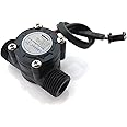
The 1/2" Water Flow Sensor is a high-performance Hall Effect flowmeter designed for a variety of applications, including water heaters and beverage machines. With a flow range of 1-30L/min and a robust pressure tolerance, this food-grade plastic sensor ensures both safety and efficiency. Its easy installation and eco-friendly materials make it a must-have for modern water management solutions.
H**R
The magic number is 897 pulses per gallon
Works. Definitely seeing the +/- 5% difference in output.A few things I discovered:* The sensor needs at least 8V. I had a 9v power supply left over from some other equipment. However, a raspberry PI can only take 3.3V into its GPIO port. (and no pull-up resistor is needed) So I sent 8V into this sensor, and on the output pin I installed a 10k resistor tied to ground. This dropped the output voltage to around 3.7V.* I wanted to record data in gallons per hour. This is from my most recent calibration where I dumped water into a bucket marked off with quarters of a gallon on the side.total_gal = total_gal + 0.001115 # 897 pulses per gal = 0.001115 gal per pulse. This code runs whenever a change from high to low occurs on the output pin.flow = (count / 897.0)*3600 # pulses/897 is gal per sec. *3600 is gal per hour* the label faces down. There is a lot of play in the spindle inside. making the label face down puts the impeller more directly in line with the water flow* make sure you install it in the right direction. The arrow on the label was correct for me.* I used waterproof automotive plugs, sealed on the ends with caulk, since this thing will be outside measuring the irrigation water usage.
B**.
Using with a reef aquarium to control flow thru a UV sterilizer
I've adapted this Gredia GR-201 1/2" flow sensor paired with a Digiten Flow Meter to monitor flow rate thru a UV sterilizer. The sterilizer I have requires a flow at 37 GPH optimum and 60 GPH max to be effective eradicating protozoa.Out of the box the pairing of the meter and sensor was way off reporting 16 GPH while a had a gate valve nearly closed.So to calibrate it, the meter has a K-factor value that has to be adjusted to the sensor you pair it with. The default was a K-factor value of 1.98.I did a Google Bard search for what the sensors K-factor should be... 11.45. I set the meters K-factor to that. It was much closer but not accurate.I adjusted my valve until the meter was reading 1 GPH of flow. I set up a bucket to divert the water exiting the system into so I could measure the amount dispensed in a minute. I recorded .453 gal. with the K- 11.45.Now a little math, divide the current K- (11.45) by the flow it produced (0.453) while the valve restricted flow with the meter reading 1 GPM.The resulting new K-factor of 25.27 worked precisely. Well, as precise as using a large measuring cup to measure the amount of water dispensed.I re-ran the test, I got 1 gallon at the 1 minute mark, 3 gal at 3 minutes.The one annoying thing about the meter is the backlit display goes dark after 15 seconds. Annoying during the calibration when your hands are busy turning on/off a pump and a timer. But in actual use I'll only be using this to set the gate valve position and the backlighting won't so much be an issue.I hope this helps those trying to get a more accurate reading.
A**R
Not perfect but for the price i have no complaints
title sums it up for me, i added enough Teflon tape, screwed everything together (no leaks) and started coding.for this project i used 2 GREDIA G2 2" Water Flow Sensor/Switch Hall Effect Flowmeter Fluid Meter Counter 10-200L/min (model GR-216). my pump is rated for about 80gpm accounting for 90degree elbows and piping i was suspecting about 60gpm all said and done. After physically measuring my flow rate and modifying my initial code i ended with a flow rate of about 57.75gpm so these get a thumps up from me.here is my initial starting off point with my Rpi3/python code wise, feel free to use it (i monster-iz-ed a couple code snip-its i found online) only thing i don't 100% understand is at the very end of the code i have to multiple gpm by 2 to get close to what i physically measured. only logic i can use is maybe this/these sensors have two pulses per rotation other than that i have no idea, it's avg. rate is at about what i measured (+-1.6%) so it's good enough for what i'm using them for.## This if for 2 GREDIA G2 2" Water Flow Sensor/Switch Hall Effect Flowmeter Fluid Meter Counter 10-200L/min (model GR-216)## This code is not 100% accurate but is close enough for measuring coolant flow in a cooling system## physically measure a flow rate of about 6.44531 gpm; sensor avg. rate is 6.342 gpm a difference of about 1.6%#!/usr/bin/python3import RPi.GPIO as GPIOimport time, sysFLOW_SENSOR = 4FLOW_SENSOR2 = 17flowCalibrationFactor = 0.2# Note: F=(0.2*Q)±2% for this flow sensor, Q=L/Min, and F is pulse freq in 1/sglobal oldTimeglobal countglobal count2oldTime = 0count = 0count2 = 0GPIO.setmode(GPIO.BCM)GPIO.setup(FLOW_SENSOR, GPIO.IN, pull_up_down = GPIO.PUD_DOWN)GPIO.setup(FLOW_SENSOR2, GPIO.IN, pull_up_down = GPIO.PUD_DOWN)def main():GPIO.add_event_detect(FLOW_SENSOR, GPIO.RISING, callback=countPulse)GPIO.add_event_detect(FLOW_SENSOR2, GPIO.RISING, callback=countPulse2)while True:try:curgpm = getFlow()print("GPM: %s" % curgpm )time.sleep(1)except KeyboardInterrupt:print('\ncaught keyboard interrupt!, bye')GPIO.cleanup()sys.exit()def countPulse(channel):global countcount = count+1def countPulse2(channel):global count2count2 = count2+1def getFlow():global countglobal count2global oldTimestart_cnt = count + count2readcnt = 0while readcnt < 1000:time.sleep(0.001)readcnt += 1end_cnt = count + count2pulses = end_cnt - start_cnt# Note: F=(0.2*Q)±2% for this flow sensor, Q=L/Min, and F is pulse freq in 1/sgpm = ((1000.0 / (round(time.time() * 1000, 5) - oldTime)) * pulses) / flowCalibrationFactor*0.26417287472922#gph = ((1000.0 / (round(time.time() * 1000, 5) - oldTime)) * pulses) / flowCalibrationFactor*15.8503pulses = 0oldTime = round(time.time() * 1000, 5)return round(gpm, 3)*2if __name__ == "__main__":main()
J**H
Too large of an obstruction reduces fluid flow
the way this unit is designed it blocks of a full 1/2 of the flow so it can direct the rest of the flow into the paddle wheel. Any time you run water through a reduced opening it causes substantial pressure drops at higher flows. The way these units should be designed is so they widen first so when the block off part of the area for the wheel it still leaves a full 1" diameter open. If they had done that it would not have caused such a large pressure drop. It may work ok if you place 3 of these parallel but that is a lot of 1" fittings to pay for.
Trustpilot
2 months ago
1 day ago